
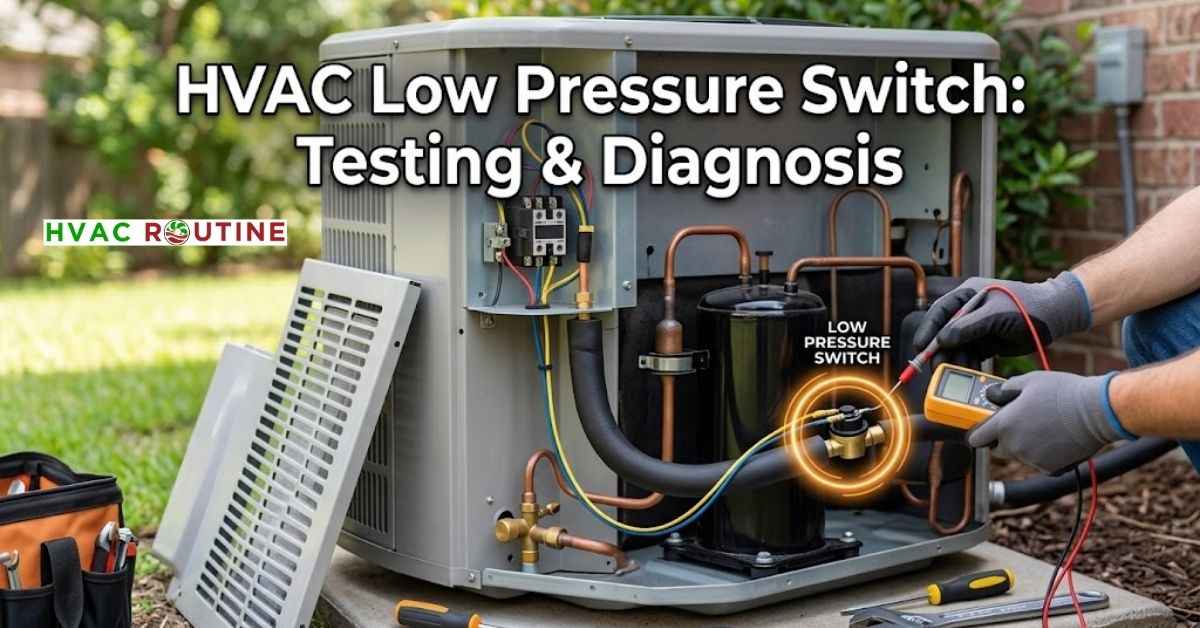
A malfunctioning HVAC low pressure switch can shut down your entire air conditioning system right in the middle of a hot summer afternoon. This small safety control acts as a sentinel for your compressor. It cuts electrical power to the outdoor unit whenever refrigerant pressure drops below safe operational limits.
Without this component, your compressor motor would overheat, lose its lubrication, and burn out within hours.
Replacing an entire compressor can easily cost upwards of two thousand dollars. Many homeowners replace two switches in a row thinking they bought defective parts, only to discover a clogged air filter caused the shutoff all along.
Learning how this safety mechanism works will save you time, money, and unnecessary stress.
Safety Warnings
- High voltage power kills, so always shut off the 240V breaker and pull the outdoor disconnect handle before touching any wiring.
- Refrigerant vapor sits under high pressure inside the copper lines.
- Wear insulated work gloves when working around service ports to prevent instant liquid refrigerant freeze burns.
- Venting refrigerant into the air violates federal environmental law under EPA Section 608 regulations.
- Never leave a jumper wire installed across safety switch terminals during normal operation.
- Running your compressor without low-side pressure protection causes permanent mechanical destruction.
Tools Required
- Digital multimeter with continuity tone and AC voltage modes
- HVAC manifold gauge set rated for R-410A, R-22, or R-32 refrigerant
- 5/16-inch and 1/4-inch insulated nut drivers
- Two adjustable crescent wrenches for brass line fittings
- Non-contact electrical voltage detector
- Insulated alligator clip test leads
- Liquid bubble leak detector solution
- Heavy-duty work gloves and eye protection
What You'll Learn ⭐⭐⭐⭐⭐
- What an HVAC Low Pressure Switch Does to Protect Your Compressor
- Automatic Reset Switches vs. Manual Reset Buttons
- Low Pressure Switch vs. Freeze Stat: Understanding the Difference
- Standard Cut-In and Cut-Out Pressure Ratings by Refrigerant
- HVAC Low Pressure Switch Location: Where to Find It
- Heat Pump Operation: Heating Mode and Defrost Cycle Nuances
- Warning Signs of a Tripped Refrigerant Low Pressure Cut Out Switch
- What Causes Low Static Pressure in HVAC Systems and Refrigerant Drops?
- How to Test HVAC Low Pressure Switch with a Multimeter?
- Step-by-Step Fixes for a Faulty Switch
- Fixing Common Airflow Triggers First
- DIY vs. Professional Repair Costs
- When to Call a Professional HVAC Technician?
- Practical Troubleshooting Summary
What an HVAC Low Pressure Switch Does to Protect Your Compressor
Your cooling system relies on a continuous loop of pressurized refrigerant to carry heat away from your living space. The HVAC low pressure switch monitors the vapor line returning to the outdoor compressor. Under standard running conditions, this switch stays normally closed.
A closed circuit allows 24-volt control power to travel directly to the contactor coil. The contactor then pulls in its heavy metal contacts and feeds 240 volts to the compressor and condenser fan motor. When the suction pressure plummets below the factory cutoff point, the internal diaphragm snaps open. An open circuit immediately breaks the 24V loop.
This sudden break drops the contactor and turns off the compressor instantly.
Automatic Reset Switches vs. Manual Reset Buttons
Most residential air conditioners utilize automatic reset switches. These switches reset the circuit on their own once internal pressures equalize and rise above the cut-in threshold. Commercial units and premium heat pumps often feature a manual reset button on top of the switch housing.
If your system trips on low pressure, this red button pops upward and locks the system off.
You must press this button down firmly to restore 24V power after you resolve the underlying problem.
Low Pressure Switch vs. Freeze Stat: Understanding the Difference
Homeowners and novice technicians frequently confuse low pressure switches with freeze protection sensors.
Both devices protect the system from freezing up, but they measure completely different physical properties.
- HVAC Low Pressure Switch: Measures actual vapor refrigerant pressure inside the sealed copper suction line. It protects against low charge, severe restrictions, and compressor starvation.
- Freeze Stat (Freeze Protection Sensor): Clamps to the outside of the indoor evaporator coil copper bends. It monitors metal surface temperature directly and opens when the coil drops to 32°F (0°C) to prevent solid ice buildup.
Standard Cut-In and Cut-Out Pressure Ratings by Refrigerant
Every refrigerant operates at a specific pressure-temperature relationship.
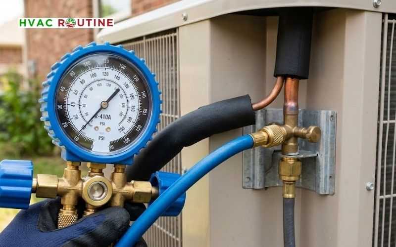
Manufacturers calibrate pressure cutouts according to the specific refrigerant running inside the lines.
| Refrigerant Type | Normal Running Suction Range | Cut-Out Pressure (System Trips) | Cut-In Pressure (System Resets) |
| R-410A | 115 – 135 PSI | 45 – 50 PSI | 80 – 100 PSI |
| R-22 | 65 – 75 PSI | 20 – 25 PSI | 45 – 55 PSI |
| R-32 | 110 – 130 PSI | 45 – 55 PSI | 85 – 105 PSI |
| R-454B | 105 – 125 PSI | 40 – 50 PSI | 80 – 100 PSI |
HVAC Low Pressure Switch Location: Where to Find It
You will find the HVAC low pressure switch location inside the outdoor condensing unit cabinet. Look for the larger copper pipe, which technicians call the suction line or vapor line. This line wears thick black foam insulation to prevent condensation from dripping everywhere.
Follow this pipe from the service valve inside toward the bottom of the compressor. The safety switch sits directly on this copper line right before the refrigerant enters the compressor housing. Two thin low-voltage wires connect directly to the switch terminals.
These control wires usually feature yellow, blue, or red insulation jackets. They run straight to the main defrost control board or wire directly in series with the compressor contactor.
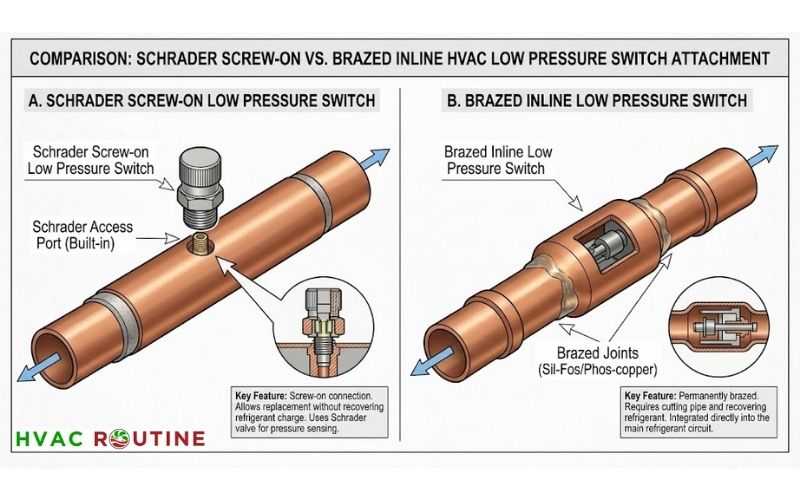
Manufacturers use two main mounting styles for these switches:
- Schrader Port Screw-On Mounts: This style screws directly onto an internal Schrader valve fitting that looks like a car tire stem. You can unscrew and replace this type quickly without releasing any refrigerant.
- Brazed Inline Mounts: Factory technicians weld this style straight into the copper tubing. Replacing a brazed switch requires a technician to recover all the system refrigerant first.
Heat Pump Operation: Heating Mode and Defrost Cycle Nuances
Heat pumps present a unique operating environment because they reverse the flow of refrigerant during winter. When running in heating mode, the outdoor coil acts as the evaporator and absorbs heat from cold outdoor air. Outdoor suction pressures naturally run much lower in winter than in summer cooling mode.
During near-freezing weather (below 35°F / 2°C), outdoor coils frost over and restrict heat absorption.
This frost layer causes suction pressures to drop sharply toward the trip threshold.
Modern heat pump control boards incorporate a bypass timer during defrost cycles. When the reversing valve shifts back to cooling mode to melt outdoor ice, pressures fluctuate rapidly. The control board ignores the low pressure input for 60 to 120 seconds.
This short delay prevents nuisance lockouts while the system stabilizes.
Warning Signs of a Tripped Refrigerant Low Pressure Cut Out Switch
A tripped refrigerant low pressure cut out switch creates distinct operational symptoms and sounds.
Pay attention to how your outdoor unit behaves when the thermostat calls for conditioning.
- Compressor Short Cycling and Contactor Chatter: The contactor vibrates and makes a rapid clicking or buzzing noise as operating pressure hovers right on the edge of the cutout point.
- Failing the Cold Suction Line Check: A healthy suction line feels ice-cold and sweats like a cold beverage can taken straight from the refrigerator. If the copper line feels lukewarm or room-temperature while the compressor runs, refrigerant flow has dropped significantly.
- Indoor Blower Runs with No Cold Air: Your indoor air handler blows room-temperature air through the supply registers while the outdoor condenser stays quiet.
- Frost and Solid Ice Accumulation: Sub-freezing suction temperatures freeze atmospheric moisture onto the indoor evaporator coil and outdoor service valves before the switch fully trips.
What Causes Low Static Pressure in HVAC Systems and Refrigerant Drops?
Both airflow restrictions and closed-loop refrigerant losses can trigger low-pressure shutoffs.
Understanding what causes low static pressure in HVAC ductwork helps you distinguish between air delivery problems and sealed system leaks.
| Fault Category | Specific Root Cause | What Happens Inside the System |
| Airflow Issues | Clogged 1-inch air filter | Starves the indoor evaporator coil of warm room air. |
| Airflow Issues | Collapsed or undersized return duct | Causes low static pressure in HVAC returns and starves the blower fan. |
| Airflow Issues | Dirty indoor evaporator coil | Blocks heat absorption, causing the refrigerant to stay liquid and pressure to drop. |
| Refrigerant Issues | Pinhole leak in copper tubing | Drops the total system charge below manufacturer specifications. |
| Refrigerant Issues | Clogged thermal expansion valve (TXV) | Pinches off refrigerant flow into the evaporator coil. |
| Refrigerant Issues | Restricted liquid line filter drier | Creates an internal blockage and a noticeable temperature drop across the drier body. |
| Weather Issues | Running AC in cold weather | Cold outdoor air below 65°F drops operating head and suction pressures naturally. |
How to Test HVAC Low Pressure Switch with a Multimeter?
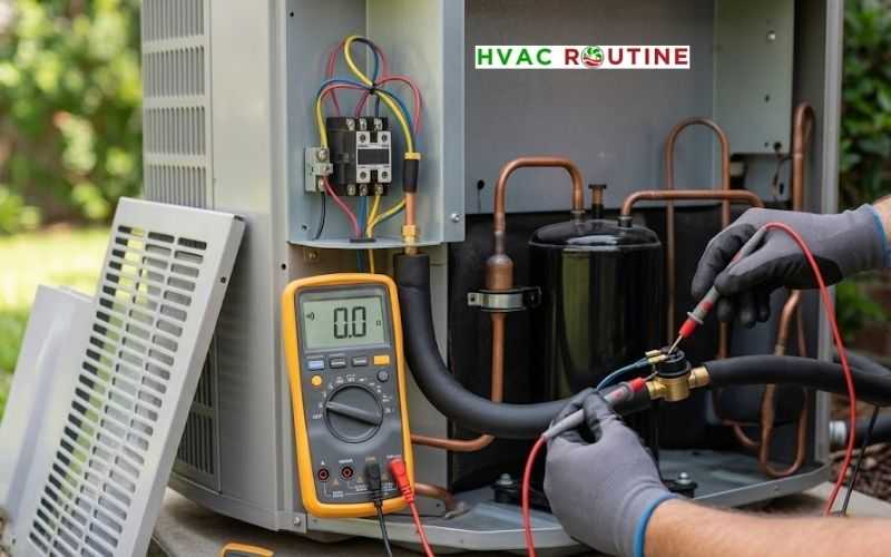
Testing this safety control takes less than ten minutes with standard diagnostic gear.
Follow this systematic field method to determine whether you have a bad switch or a genuine mechanical breakdown.
1. Measure Control Voltage Drop
Turn the indoor thermostat down so it calls for cooling. Leave the main power on and locate the two electrical terminals on the safety switch. Set your digital multimeter to measure AC voltage on the 0-50V scale.
Place one meter probe on each terminal of the switch. If your meter reads 0 volts, the switch contacts are closed and conducting current properly. If your meter reads 24 volts, the switch contacts have opened and broken the circuit.
2. Perform an Unpowered Continuity Check
Turn off the outdoor disconnect switch and verify zero power with your non-contact tester. Pull one wire off the switch spade terminal to eliminate backfeeding through other components. Switch your multimeter to the continuity tone or resistance (Ohms) setting.
Touch the test leads across both bare switch terminals. A continuous tone or a reading between 0.0 and 0.3 Ohms confirms a closed, operational switch. A display showing “OL” or infinite resistance means the internal contacts remain open.
3. Verify System Pressure with Manifold Gauges
Connect your blue low-side manifold gauge hose to the suction service port on the large copper line. Read the actual standing or running pressure on the dial face. Compare this number with the cutout pressure printed directly on the side of the switch body.
If your gauge shows 25 PSI on an R-410A system, the open switch is doing its job correctly. If your gauge shows 120 PSI and the switch remains open, the internal sensing diaphragm has failed.
4. Run a Brief Diagnostic Jumper Confirmation
Keep high voltage power turned off before attaching any test jumpers. Attach an insulated alligator jumper wire across the two switch wire terminals. Step back, restore power, and observe the compressor contactor.
If the compressor starts and runs smoothly, you have verified an open circuit on that safety leg. Remove the jumper wire immediately after ten seconds of observation.
Step-by-Step Fixes for a Faulty Switch
Follow these clear procedures to resolve pressure switch lockouts safely.
Fixing Common Airflow Triggers First
- Slide out your dirty air filter and insert a fresh, clean replacement with the airflow arrow pointing toward the blower.
- Open all supply registers and make sure return grilles remain unobstructed by furniture, drapes, or rugs.
- Inspect the indoor evaporator coil fins and clean off any thick blankets of household dust using a soft brush.
- Let frozen evaporator coils thaw completely before restarting your air conditioning equipment.
Replacing a Threaded Schrader-Mount Switch
- Shut off electrical power at both the indoor air handler breaker and the outdoor service disconnect box.
- Put on protective leather work gloves to shield your fingers from sudden refrigerant burps.
- Label the two control wires and slide their spade connectors off the old switch terminals.
- Hold the lower brass base fitting firmly with one wrench to protect the copper tubing from twisting.
- Place your second wrench on the switch body nut and turn it counterclockwise.
- Unscrew the old switch swiftly to minimize refrigerant discharge from the Schrader core pin.
- Check the new switch to make sure the internal rubber sealing O-ring sits flat inside the fitting.
- Never apply white Teflon tape or pipe dope to these threads, as shredded tape blocks the internal valve pin and prevents the rubber gasket from sealing.
- Spin the new switch onto the threads by hand to avoid cross-threading the brass fitting.
- Tighten the switch body one-quarter turn past hand-tight with your wrench.
- Apply liquid bubble leak detector solution to verify a bubble-free seal around the threads.
- Slide the control wires back onto the spade terminals securely.
- Restore electrical power and verify that the system runs smoothly.
DIY vs. Professional Repair Costs
Understanding the cost breakdown helps you decide whether to tackle this repair yourself or hire a professional contractor.
- DIY Threaded Switch Replacement: A replacement screw-on switch costs between $15 and $45 online or at local supply stores.
- Standard Professional Service Call: A licensed technician charges between $150 and $350 for diagnostic inspection and screw-on switch replacement.
- Brazed Inline Switch Replacement: Replacing a welded switch costs between $400 and $750 because the job requires refrigerant recovery, torch brazing, nitrogen purging, deep vacuum evacuation, and recharging.
- Refrigerant Leak Repair and Recharge: Locating and fixing a coil leak ranges from $500 to $1,800 depending on the severity and location of the copper fracture.
When to Call a Professional HVAC Technician?
Some mechanical and chemical repairs require specialized licensing, recovery machinery, and formal certifications.
Contact a licensed cooling technician whenever you encounter the following conditions:
- Your manifold gauges read zero or drop straight into a vacuum, which signals a massive refrigerant leak.
- Your unit uses a brazed inline pressure switch that requires cutting and oxy-acetylene torch work.
- Finding hidden pinhole leaks requires pressurized dry nitrogen decay tests and ultrasonic leak detectors.
- Replacing lost refrigerant requires formal EPA Section 608 universal technician credentials.
- The compressor housing feels extremely hot to the touch, which suggests contaminated oil or acid buildup inside the crankcase.
Practical Troubleshooting Summary
Treat your safety switch as an informative messenger rather than the primary culprit. In roughly eight out of ten service calls, an open low-pressure cutout indicates real trouble with airflow delivery or refrigerant volume.
Check your air filters, inspect your ductwork, and verify true line pressures before you condemn the switch itself. Following these methodical steps protects your compressor from expensive damage and keeps your cooling system running strong all summer long.

2 thoughts on “Complete HVAC Low Pressure Switch Guide: Location, Testing, and Fixes”