Quick 30-Second Reset Summary
- Point your handheld remote at the indoor wall unit and hold down the CANCEL button for five seconds until 00 flashes on the screen.
- Tap CANCEL repeatedly until the unit emits a long, continuous beep at code C9.
- Switch off the main double-pole HVAC breaker at your electrical panel for a full five minutes to drain the control board capacitors.
- Restore breaker power and turn the unit back on with your remote.
- If the green light starts blinking again within three minutes, perform a multimeter resistance check or replace the suction air thermistor.
What You'll Learn ⭐⭐⭐⭐⭐
- Project Snapshot: Diagnostic & Repair Specs
- What Does the Daikin C9 Error Code Actually Mean?
- Don’t Confuse C9 with C4 or C5 Faults
- How to Confirm the C9 Code on Your Controller
- Wireless Handheld Remote
- Wired Wall Controllers (BRC1E, BRC1D, and Madoka Series)
- Daikin C9 Error Code Reset: 3 Proven Field Methods
- Safety Warnings and Essential Tools
- Technician-Level Testing: Resistance and the 5V DC Board Check
- Finding the Correct OEM Replacement Part
- Step-by-Step Sensor Replacement Guide
- Never Bypass the Thermistor with a Fixed Resistor
- Daikin C9 Troubleshooting Reference Matrix
- When to Call an HVAC Professional
- Frequently Asked Questions
- Can I run my Daikin mini-split while the C9 error code displays?
Project Snapshot: Diagnostic & Repair Specs
| Specification | Details |
| Project Difficulty | Beginner to Intermediate (DIY-friendly) |
| Estimated Time | 15 to 30 minutes |
| Estimated Cost | $20 – $45 (DIY OEM Sensor) vs. $175 – $325 (Professional Service Call) |
| Primary Tools Needed | Digital Multimeter, #2 Phillips Screwdriver, Room Thermometer |
| System Component | Indoor Suction Air Thermistor (Room Temperature Sensor) |
Few things feel more discouraging than walking into your living room on a humid, 90-degree afternoon only to discover your mini-split blowing tepid, room-temperature air. You glance up at the indoor unit and spot the dreaded blinking green operation light. When you pull up the remote diagnostics and discover you are dealing with a suction air sensor fault, a proper Daikin C9 error code reset is your first step toward restoring cold airflow.
Sometimes a momentary utility brownout scrambles the indoor microcomputer, and a quick reboot resolves the issue immediately. Other times, years of thermal cycling have worn out the internal sensor element, or dust has blanketed the probe.
Whether you are a hands-on homeowner trying to avoid an expensive weekend service call or a property manager troubleshooting multiple units, this guide covers everything you need: from quick controller resets to multimeter bench testing and OEM sensor replacement.
What Does the Daikin C9 Error Code Actually Mean?
Inverter mini-splits rely on a network of solid-state sensors to operate efficiently. Unlike older central AC systems that simply cycle on and off based on a wall thermostat, a Daikin mini-split constantly calculates compressor speeds and meters refrigerant flow in real time.
The C9 fault code indicates that your indoor suction air thermistor circuit has opened, shorted out, or drifted completely outside its engineered resistance parameters. Field technicians commonly refer to this part as the indoor room temperature sensor.
This sensor mounts on a small plastic bracket directly in front of the upper evaporator coil, right behind your slide-out air filters. It measures the precise temperature of the ambient air entering the return grille before that air hits the cold coil fins. The indoor printed circuit board (PCB) uses this measurement as its baseline to calculate heating or cooling demand. When this reading drops out, the microcomputer immediately locks out the outdoor compressor to prevent the indoor coil from freezing into a solid block of ice.
Don’t Confuse C9 with C4 or C5 Faults
Daikin indoor heads contain three distinct thermistors, and DIYers frequently mix them up when ordering replacement parts:
- C9 Fault: Monitors the suction air thermistor (measures ambient room return air).
- C4 Fault: Monitors the indoor heat exchanger liquid pipe thermistor (measures refrigerant temperature at the distributor).
- C5 Fault: Monitors the indoor heat exchanger gas pipe thermistor (measures suction vapor temperature at the coil header).
Both the C4 and C5 sensors clamp directly onto copper piping buried inside the coil assembly. If your remote displays C9, leave those copper pipe sensors alone. You are troubleshooting the free-hanging black sensor bead on the face of the coil.
How to Confirm the C9 Code on Your Controller
Before taking anything apart, confirm that C9 is the active fault code halting your system.
Wireless Handheld Remote
Grab your wireless remote and point it straight at the indoor head unit. Locate the small CANCEL button near the bottom of the keypad. Press and hold that button down for five seconds until the normal display disappears and two flashing zeros (00) take its place.
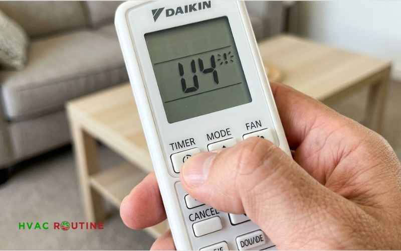
Now, tap the CANCEL button slowly to step through the system’s fault code list. The indoor unit will let out a short, single chirp for every normal code. When you reach the active fault code—in this case, C9—the unit will sound a continuous, loud beep. Press the power button once to exit the diagnostic menu.
Wired Wall Controllers (BRC1E, BRC1D, and Madoka Series)
Ducted mini-splits and light-commercial setups usually feature hardwired wall controllers rather than handheld remotes.
- BRC1D52 Series: Press and hold the TEST/OPERATION button for four to five seconds until the wrench icon and the active fault code appear in the center of the display.
- BRC1E73 (Navigation Remote): The controller will display an “Error: Push Menu Button” message alongside a solid red warning indicator. Press the Menu/Enter button to pull up the primary fault screen, which clearly displays the error code and unit address.
- Daikin Madoka: Open the Madoka app on your smartphone via Bluetooth, select your indoor unit, and tap the status banner to read the active error log directly from your screen.
Field Pro-Tip: On floor consoles or ceiling cassettes without digital displays, check the indoor control board LEDs. A steadily blinking green operation LED combined with nine distinct flashes from the red diagnostic LED confirms a C9 suction thermistor failure.
Daikin C9 Error Code Reset: 3 Proven Field Methods
An electrical storm, grid fluctuation, or minor utility brownout can freeze the indoor board’s memory without actually damaging any components. Try these three reset methods before ordering replacement parts.
Method 1: The Remote Controller Soft Reset
If the system encountered a transient voltage spike, a quick soft reset can clear the board’s short-term fault register:
- Aim your remote directly at the indoor receiver and turn the unit off.
- Hold down the CANCEL button for five seconds until you reach the diagnostic menu.
- Tap CANCEL repeatedly until the display cycles past the error list and returns to the standard home temperature screen.
- Press the primary power button to fire up the system.
If the issue was just a software hiccup, your outdoor unit will engage its reversing valve, spin up the fan, and start cooling within three minutes.
Method 2: The Wired Controller Reset
For wall-mounted BRC controllers, press the Menu/Enter button and navigate to the Maintenance sub-menu. Select Reset Inspection Indicator (or Clear Error History on newer models) and confirm with the enter button. The controller will send a clear command across the P1/P2 communication bus to reboot the indoor board’s monitoring loop.
Method 3: The 5-Minute Circuit Breaker Hard Reset
Soft resets via the remote only clear the display register; they do not discharge the high-capacity direct-current capacitors soldered to the indoor and outdoor control boards. To perform a true hardware-level Daikin C9 error code reset, you need to cut power at the source.
Head to your main electrical panel and find the double-pole breaker powering your mini-split. Switch it firmly to the OFF position.
Now, wait a full five minutes. This waiting period is critical: modern inverter boards retain DC voltage in their large smoothing capacitors for several minutes after AC power drops. Rushing this step will leave residual memory intact and defeat the reset.
Flip the breaker back to ON. Give the outdoor unit two minutes to complete its boot sequence and run its sensor sweep, then turn the system on using your remote. If the unit runs normally and keeps cooling, a temporary electrical surge caused your shutdown.
Safety Warnings and Essential Tools
Before opening up your indoor unit to test or replace the sensor, review these basic precautions:
- Turn off the power: Mini-split indoor units receive high-voltage 208V/230V power directly from the outdoor unit across terminals 1 and 2 of the main terminal block. Always verify that power is dead using a non-contact voltage tester before removing electrical covers.
- Watch the plastic latches: Indoor plastic housings become brittle after three or four years of exposure to indoor air and temperature changes. Release the casing tabs gently using a nylon trim tool to avoid snapping the mounting hooks.
- Ground yourself: Touch an unpainted metal screw on the chassis before touching the control board to prevent electrostatic discharge (ESD) from damaging the microprocessors.
Recommended Diagnostic Tools
- A digital multimeter with fine-point needle probes.
- A standard digital room thermometer.
- A #2 Phillips screwdriver.
- A nylon trim pry tool or plastic putty knife.
Technician-Level Testing: Resistance and the 5V DC Board Check
If the error code returns within three minutes of a breaker reset, you have a physical hardware issue. Rather than guessing whether you need a new sensor or an expensive control board, run these two quick multimeter tests.
Test 1: The 5V DC Reference Voltage Check
Before blaming the thermistor, make sure the indoor control board is actually sending power to it:
- Turn off the circuit breaker and remove the plastic front cover from your indoor head.
- Remove the metal service cover on the right side to expose the indoor PCB.
- Trace the thin black or yellow wires from the suction sensor to the two-pin socket labeled S20 or X15A on the board.
- Unplug the plastic sensor connector from the board header.
- Turn the circuit breaker back on, keeping your hands away from the high-voltage terminal block.
- Set your multimeter to DC Volts and touch your meter probes to the two bare metal header pins on the board.
A healthy Daikin board outputs a steady 4.8 to 5.1 Volts DC. If your meter reads 0V, the analog-to-digital circuit on the control board has failed, meaning you need a board replacement rather than a new sensor. If you read 5V DC, your board is working properly, confirming the issue lies within the thermistor harness itself. Turn the breaker back off before continuing.
Test 2: Multimeter Resistance vs. Temperature Check
Daikin uses Negative Temperature Coefficient (NTC) thermistors. As the air temperature rises, the sensor’s electrical resistance drops.
Set your multimeter to kilo-ohms (kΩ). Insert your probe tips directly into the two tiny female pin slots of the disconnected sensor harness plug. Check your room thermometer and compare your multimeter reading against this factory reference chart:
| Ambient Room Temperature | Target Resistance | Acceptable Range |
| 50°F / 10°C | 39.5 kΩ | 38.0 – 41.0 kΩ |
| 59°F / 15°C | 30.8 kΩ | 29.5 – 32.0 kΩ |
| 68°F / 20°C | 24.2 kΩ | 23.5 – 25.0 kΩ |
| 77°F / 25°C (Factory Baseline) | 20.0 kΩ | 19.6 – 20.4 kΩ |
| 86°F / 30°C | 16.0 kΩ | 15.4 – 16.6 kΩ |
| 95°F / 35°C | 13.0 kΩ | 12.4 – 13.5 kΩ |
The Warm-Thumb Test
Keep your test probes inserted into the sensor plug and pinch the small black sensor bead firmly between your thumb and forefinger. Your body heat will warm the sensor within ten seconds.
Watch the multimeter display: on a healthy sensor, the resistance will drop smoothly and continuously as the probe warms up. If your meter reads 0.00 Ω (dead short), displays OL (open loop / broken internal lead), or stays completely frozen at one value, replace the sensor harness.
Finding the Correct OEM Replacement Part
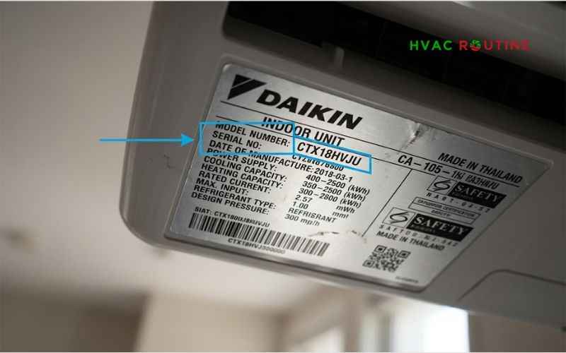
Avoid buying unbranded, generic thermistors from discount online marketplaces. Generic sensors rarely match Daikin’s specific NTC resistance curve, which tricks the inverter into running at incorrect speeds and can spike your electric bill.
Check the silver rating plate located on the bottom or side of your indoor unit’s casing to find your exact model number (e.g., FTXS12LVJU, FTX09AXVJU, or CTX15AXVJU).
Common Daikin factory part numbers include:
- Daikin 138856J / 1388562: The standard suction air thermistor assembly found on most FTXS and FTX wall-mounted units.
- Daikin 99A0284: Return air sensor harness tailored for multi-split indoor evaporator heads.
- Daikin 1601323: Heavy-duty ambient sensor harness used on light-commercial and slim-duct indoor units.
Step-by-Step Sensor Replacement Guide
Replacing this sensor takes about twenty minutes and requires only a screwdriver and a little patience.
- Cut Power: Turn off the double-pole HVAC breaker at your electrical panel and verify zero voltage at the indoor unit.
- Remove the Fascia: Open the front intake grille, pull out both mesh filters, and remove the lower horizontal louver vanes. Unscrew the two or three Phillips screws along the lower lip of the chassis, gently pop the top latches using your pry tool, and lift the plastic cover off.
- Unclip the Old Sensor: Locate the black teardrop sensor bead clipped onto the front face of the aluminum coil. Slide the bulb upward out of its bracket. Be careful not to bend the delicate aluminum fins behind it.
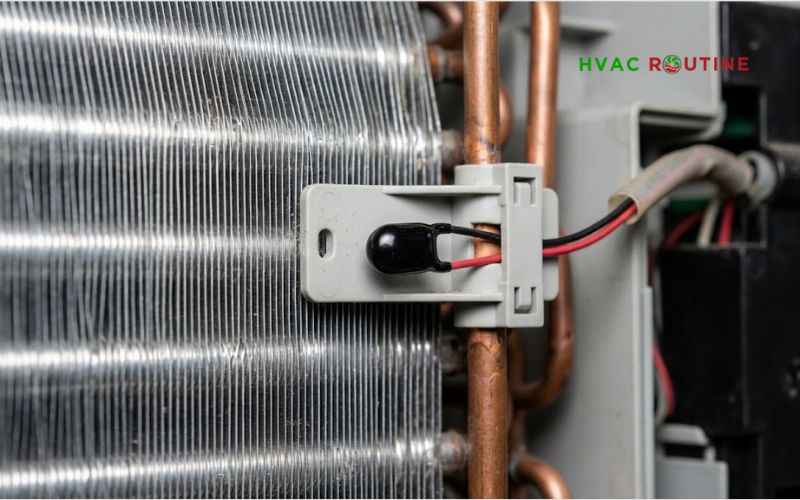
- Disconnect the Harness: Open the galvanized control box lid, depress the locking tab on the S20 or X15A header, and unplug the harness from the PCB.
- Install the New Sensor: Plug the new harness connector firmly into the board header until you hear an audible click. Route the wiring through the molded plastic tracks on the drain pan to keep it safely clear of the spinning blower wheel.
- Snap the Bulb in Place: Click the new sensor bulb into the coil mounting bracket.
- Reassemble and Test: Replace the metal electrical lid, reinstall the front plastic housing, reinsert your clean air filters, and restore breaker power. Fire up the unit in cooling mode and let it run for fifteen minutes to verify stable operation.
Never Bypass the Thermistor with a Fixed Resistor
You might come across forum posts suggesting that you can bridge the board pins with an inexpensive 20 kΩ resistor to bypass the sensor. Do not do this.
Daikin’s microcomputer constantly compares the return air temperature against the indoor coil pipe temperatures. If the board detects that the room air temperature remains frozen at 77°F while the indoor coil plunges to 34°F, it will recognize an airflow failure. The system will shut down on an auxiliary code, or the indoor coil will freeze over entirely, potentially sending liquid refrigerant back to the compressor and destroying it.
Daikin C9 Troubleshooting Reference Matrix
| Symptom | Probable Cause | Corrective Action |
| Blinking green light after electrical storm | Logic freeze in board processor | Perform a 5-minute circuit breaker hard reset |
| Error returns immediately after reset | Disconnected or severed sensor wire | Inspect header S20 or X15A on the indoor board |
| Multimeter displays “OL” during test | Broken internal thermistor element | Install an authentic OEM factory sensor harness |
| Board header reads 0V DC during test | Blown circuit board power rail | Replace the indoor main printed circuit board |
| Heavy dust blanket over sensor bulb | Restricted air intake flow | Wash the mesh air filters under warm running water |
When to Call an HVAC Professional
While replacing a thermistor is well within reach for most DIYers, certain scenarios warrant a professional service call:
- Failed Board Voltage: If your multimeter measures 0V DC across the S20 header pins, the indoor main board requires replacement. Working on board circuitry often requires specialized static control and system configuration.
- Active Factory Warranty: If your equipment is less than five or ten years old, unauthorized component replacements can void your parts coverage. Let an authorized dealer handle the warranty claim.
- Burnt Electrical Odors: If you smell scorched insulation or spot blackened solder joints inside the metal control box, an electrical short has occurred that requires professional evaluation.
Frequently Asked Questions
Can I run my Daikin mini-split while the C9 error code displays?
No. The indoor control board locks out the outdoor compressor as an automated safeguard whenever it registers an active C9 code. The indoor fan might continue circulating unconditioned air, but the system will not heat or cool until the fault clears.
Where is the indoor room temperature sensor located on a Daikin unit?
The sensor sits behind the front intake grille, clipped to a plastic bracket right on the face of the aluminum evaporator coil. You can see it as soon as you swing open the front decorative panel and slide out the right-side mesh filter.
How much does it cost to fix a Daikin C9 error?
If you diagnose and replace the sensor yourself, an authentic OEM Daikin thermistor harness costs between $20 and $45. If you hire a licensed HVAC technician, expect to pay between $175 and $325, which covers diagnostic time, labor, and the replacement part.