
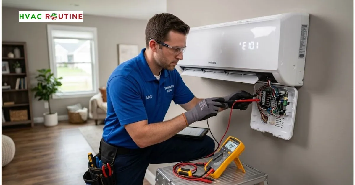
Few household headaches match the frustration of walking into your living room on a sweltering July afternoon only to discover your air conditioner blowing room-temperature air. When your indoor unit shuts its louvers and begins flashing the Samsung E101 error code, your ductless mini-split system has suffered a breakdown in serial data communication between the indoor evaporator and the outdoor condensing unit. In plain terms, the indoor circuit board stopped receiving digital data packets from the outdoor unit for more than sixty continuous seconds.
You will frequently see this fault alongside the related Samsung E202 error code, which indicates that the outdoor condenser cannot track or establish a handshake with an indoor head. If your system syncs with the Samsung SmartThings app, your phone will alert you to an “Outdoor Unit Communication Error.” Before you assume the worst and drop hundreds of dollars on a brand-new printed circuit board, take a breath. In our field experience, a huge percentage of these communication faults stem from minor issues—like loose terminal screws, electrical noise, or a fried fuse—that you can diagnose and repair with a standard multimeter, basic hand tools, and a methodical checklist.
What You'll Learn ⭐⭐⭐⭐⭐
- Quick Terminology Guide
- Affected Samsung Mini-Split and VRF Models
- Decoding E101 and E202 on Displays and Status LEDs
- 1. The Outdoor 7-Segment Readout
- 2. Units Without a Digital Screen (The 3-LED Front Panel)
- Checking Error Codes on Samsung Wired Wall Controllers
- What Causes the Samsung E101 Error Code?
- Understanding the Samsung E202 Error Code and Tracking Failures
- Terminal Confusion: Never Mix Up F1/F2 with F3/F4 or V1/V2
- Cable Rules: Wire Gauge, Shielding, and Distance Limits
- Safety Protocol: Discharging High-Voltage Inverter Capacitors
- Step-by-Step Fix 1: Perform the 5-Minute Inverter Power Drain
- Step-by-Step Fix 2: Run Dead-Line Resistance and Continuity Tests
- The Short-Circuit Test
- The Loop Continuity Test
- Step-by-Step Fix 3: Test Live DC Signal Voltage with a Multimeter
- Step-by-Step Fix 4: Inspect the Outdoor PCB, Fuses, and Optocouplers
- How to Find the Exact Samsung OEM PCB Part Number
- Step-by-Step Fix 5: Reprogram the 24-Digit Samsung Option Code
- How to Find Your Code If the Sticker Is Missing
- Step-by-Step Fix 6: Clear Multi-Zone E202 Tracking Errors
- Preventive Upgrades: Surge Protectors and Pest Guards
- Estimated Repair Costs: DIY vs. Professional Service
- Can I run my communication wire inside the same conduit as the line-voltage power wire?
- When to Call a Certified HVAC Technician
- Final Troubleshooting Summary
Quick Terminology Guide
- PCB (Printed Circuit Board): The main microcomputer board that manages operating voltages, reads thermistor sensors, and modulates inverter compressor speeds.
- EEPROM: A non-volatile onboard memory chip that permanently stores factory model profiles and option codes even after total power loss.
- Optocoupler: A miniature electronic switch that transmits digital data pulses using internal light beams, physically isolating delicate microprocessors from high-voltage spikes.
- STP (Shielded Twisted Pair): High-grade communication cable encased in a metallic foil wrap with a bare drain wire, designed specifically to block electromagnetic interference.
- Daisy-Chain: A clean, point-to-point wiring method connecting equipment in series without splices, wire nuts, or branching T-taps.
Affected Samsung Mini-Split and VRF Models
Both compact single-zone residential units and massive commercial variable refrigerant flow (VRF) systems communicate over Samsung’s proprietary F1/F2 serial protocol. Recognizing your exact platform will help you locate the right diagnostic points and wiring blocks.
| System Category | Popular Series / Model Prefixes | Typical Communication Topology |
| WindFree Residential Single-Zone | AR09, AR12, AR18, AR24 (Wall Mounts) | Dedicated 2-wire F1/F2 line directly to outdoor condenser |
| Legacy Mini-Split Systems | Max, Quantum, Vivace, Whisper Series | Direct point-to-point F1/F2 terminal connections |
| Free Joint Multi (FJM) | AJ020, AJ024, AJ036 Condensers (Multi-Zone) | Multi-tap F1/F2 bus connecting multiple indoor evaporators |
| Commercial VRF / Light Commercial | DVM S, DVM S2, CAC Cassettes, Ducted Units | Central Daisy-Chain serial network loop with automated addressing |
Decoding E101 and E202 on Displays and Status LEDs
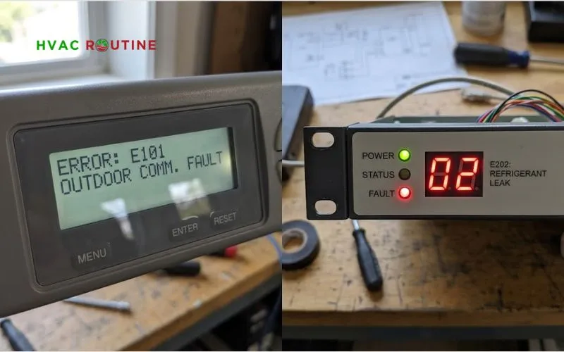
Depending on your model, your equipment will display diagnostic codes across three primary hardware interfaces: front fascia digital displays, outdoor service board readouts, or blinking status LEDs.
1. The Outdoor 7-Segment Readout
Most multi-zone and light commercial condensing units feature a small red digital LED display directly on the inverter board. When an active fault occurs, this display alternates between two-character segments to describe the issue.
- An alternating
E1followed by01confirms that the indoor evaporator has stopped receiving packets. - An alternating
E2followed by02(orC202) indicates that the outdoor condenser lost tracking communication with indoor head number two.
2. Units Without a Digital Screen (The 3-LED Front Panel)
Many popular single-zone models, including several WindFree units, omit numeric digital displays to keep the front profile sleek. Instead, they signal faults using three front-panel indicator lights: Operation, Timer, and Turbo/Option.
| Error Code | Operation Lamp | Timer Lamp | Turbo / Option Lamp | Meaning |
| E101 | Blinking | OFF | Blinking | Indoor board receives zero data packets |
| E202 | OFF | Blinking | Blinking | Outdoor condenser lost communication tracking |
A blinking lamp flashes on and off once every half-second. If you see all three lamps flashing simultaneously at the exact same rhythm, your indoor control board has suffered a complete memory corruption rather than a simple line drop.
Checking Error Codes on Samsung Wired Wall Controllers
Commercial properties and custom homes frequently swap standard wireless handheld remotes for hardwired wall controllers like the MWR-WE10N or MWR-SH11N. These wired units provide direct access to an internal field service menu that pinpoints offline hardware in seconds.
To access this diagnostic screen, press and hold the Set and Cancel buttons together on your wired remote for five seconds. The controller screen will switch into Field Service Display Mode. The top display segment shows the indoor unit tracking address (00, 01, 02, etc.), while the bottom segment flashes the active error code. If you see E101 flashing next to address 02, for instance, you know immediately that zone three has dropped offline while your main controller remains functional.
What Causes the Samsung E101 Error Code?
Think of the F1 and F2 communication line like two people speaking over a two-way radio. Every few milliseconds, the indoor board asks for a specific compressor speed and reports coil temperatures, and the outdoor board immediately replies with operational feedback. If the outdoor board goes silent for sixty consecutive seconds, the indoor unit assumes the outdoor compressor is blind or in danger, halts operation, and throws the Samsung E101 error code.
When diagnosing this sudden silence in the field, we typically trace the root cause back to a handful of everyday issues:
- Voltage Disturbances: Severe utility grid sags or nearby lightning storms scramble the temporary memory registers inside the microprocessors.
- Vibration and Thermal Expansion: Terminal screws back out over time due to constant compressor vibration, breaking physical contact with the copper wire.
- Corroded Terminals: Moisture intrusion creates green copper oxidation, adding resistance that smothers delicate direct-current communication pulses.
- Physical Cable Damage: Rodents chew through insulation, landscapers nick exposed lines with weed trimmers, or sharp cabinet sheet metal cuts into the jacket.
- Electromagnetic Induction (EMI): Installers run cheap, unshielded wire right alongside high-voltage 240V power lines, scrambling the digital data stream.
- Blown Control Fuses: A shorted power circuit on the outdoor inverter board pops the low-amperage protective fuse, cutting power to the communication loop.
- Damaged Optocouplers: A utility surge bridges the board’s protective circuits and fries the sensitive optical communication chips.
Understanding the Samsung E202 Error Code and Tracking Failures
While an E101 error originates from the indoor unit’s perspective, the Samsung E202 error code represents the outdoor condenser’s side of the conversation. When you energize the system, the outdoor master processor runs an automated tracking routine, querying the refrigerant network to register every connected indoor head.
The condenser trips an E202 error when it loses communication with an indoor unit that it previously recognized during its tracking cycle. We see this happen constantly on multi-zone Free Joint Multi (FJM) setups. Imagine a four-zone condenser cooling an entire home: if a painter turns off the local wall switch for the guest bedroom to paint around the unit, the outdoor condenser suddenly loses contact with that zone. Because the outdoor unit cannot verify coil temperatures or safety valve positions on the missing head, it halts cooling across the entire home. Crossed signal wiring, duplicate zone dip-switch addresses, and damaged indoor power feeds will also trigger an E202 tracking halt.
Terminal Confusion: Never Mix Up F1/F2 with F3/F4 or V1/V2
One of the most expensive diagnostic mistakes we see DIYers make is testing or connecting wires to the wrong terminal blocks. Samsung electrical compartments contain multiple low-voltage terminal strips that look identical to an untrained eye.
- F1 and F2: These terminals route the low-voltage, bipolar digital data stream between the indoor evaporator and the outdoor condenser.
- F3 and F4 (or V1 and V2): These terminals supply 12V DC power and serial instructions to wired wall remotes, centralized controllers, and Wi-Fi modules.
- L and N (or 1 and 2): These high-voltage terminals route 208/240-volt alternating current to power the equipment motors and compressor.
Pro-Tip: Take a clear, well-lit photo of your terminal block on your smartphone before loosening any screws. Mixing up the outdoor communication wire with the 12V wall controller terminals can feed improper voltage into delicate receiver circuits, permanently destroying the communication transceiver chips on the PCB.
Cable Rules: Wire Gauge, Shielding, and Distance Limits
Inverter mini-splits do not tolerate cut-rate wiring. Because variable-frequency compressor drives produce significant electrical switching noise, Samsung factory engineering specifications demand 16 AWG or 18 AWG 2-core stranded, shielded twisted-pair (STP) cable. Ordinary solid-core thermostat wire is a major liability; it snaps easily under mechanical vibration and lacks the aluminum shielding required to block electrical noise.
Always observe these factory distance and layout rules:
- Single-Zone Distance Limit: Keep the total communication line run between the indoor and outdoor units under 50 meters (164 feet).
- Commercial DVM S Network Limit: Limit your total interconnected serial loop across all units to 1,000 meters (3,280 feet).
- Strictly No T-Taps: Never branch communication wires with wire nuts into star configurations or T-taps.
- Daisy-Chain Routing Only: Run your communication cable cleanly from the outdoor condenser into indoor unit one, then loop out of unit one into unit two in a continuous chain.
- The Single-Ground Rule: Connect the bare shield drain wire to the chassis ground screw only at the outdoor unit. If you ground the shield wire at both ends, you create an electrical ground loop that pulls line noise directly into the communication circuit.
Safety Protocol: Discharging High-Voltage Inverter Capacitors
Ductless air conditioners convert incoming alternating current into direct current, powering variable-speed motors through high-voltage inverter circuits. The large electrolytic capacitors mounted on the outdoor board store lethal levels of direct current—often up to 400 volts DC—long after you flip the breaker.
Never treat this equipment casually. Before touching terminal connections, flip the dedicated dual-pole breaker inside your main service panel to OFF. Walk outside to the condensing unit and pull the disconnect handle completely out of the box. Most importantly, wait at least five full minutes before removing cabinet covers. This mandatory waiting window gives the internal bleeder resistors time to drain dangerous DC voltages down to a harmless 5 volts. Always wear safety glasses and insulated electrical gloves rated for 1,000 volts.
Step-by-Step Fix 1: Perform the 5-Minute Inverter Power Drain
Microprocessors inside modern control boards handle hundreds of calculations every second. Lightning strikes, sudden utility brownouts, or rapid power flickers can scramble temporary memory registers, leaving the microprocessor stuck in an unrecoverable logic loop. Performing a hard cold reset flushes these memory chips clean.
- Turn off your air conditioner using your handheld remote or wall controller.
- Head to your main electrical panel and flip the dedicated air conditioner breaker to OFF.
- Walk out to the outdoor condensing unit and pull the disconnect block out of its housing.
- Leave the power dead for a full five minutes. This time window ensures that internal capacitors drain completely, forcing the microprocessor to dump its temporary memory registers and execute a fresh boot cycle.
- Reinstall the outdoor disconnect block and switch your main breaker back to ON.
- Power on the system using your remote control and set it to Cool Mode at 72°F.
- Wait at least three minutes for the internal compressor anti-short-cycle delay to expire. If a temporary voltage glitch caused your issue, your mini-split will fire up and blow cold air right away.
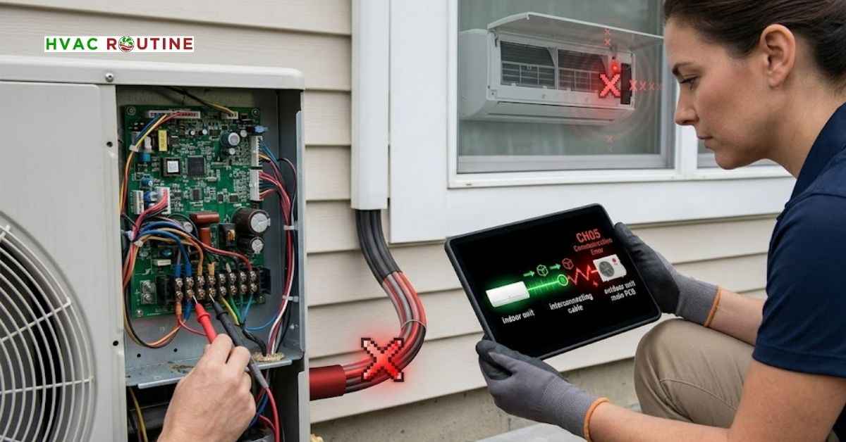
Step-by-Step Fix 2: Run Dead-Line Resistance and Continuity Tests
If cycling the power does not clear the error code, you must test the physical cable for broken copper strands or internal shorts. You can perform these resistance tests with your multimeter while the power remains completely off.
First, turn off power at the main breaker, wait your five-minute safety window, and remove the F1 and F2 wires from the terminal blocks at both the indoor and outdoor units. Set your digital multimeter to measure Resistance / Ohms ($\Omega$).
The Short-Circuit Test
Leave the bare wire ends at the indoor unit completely separated in the air so they touch nothing. Walk out to the outdoor unit and place your multimeter probes across the bare F1 and F2 wire ends.
- Normal Result: Your meter must read Open Loop ($OL$) or infinite Mega-Ohms, proving the two internal wires are isolated from one another.
- Faulty Result: If you read any measurable resistance (such as 50 Ohms or zero Ohms), the internal insulation has melted, crushed, or worn through, shorting the communication pair inside the wall.
The Loop Continuity Test
Walk indoors and twist the bare copper ends of F1 and F2 firmly together into a temporary splice. Return outside to your condenser and place your meter probes across the outdoor F1 and F2 wire ends.
- Normal Result: Your meter should read under 10 Ohms ($\Omega$), confirming a continuous, low-resistance loop.
- Faulty Result: If your meter shows an $OL$ or high resistance reading (hundreds of Ohms), one of the copper conductors has snapped clean through or developed heavy corrosion inside the line set.
Step-by-Step Fix 3: Test Live DC Signal Voltage with a Multimeter
Once your wiring passes resistance testing, reconnect the F1 and F2 wires firmly to their respective terminals. Now you need to determine whether the boards are actually pulsing digital communication commands over the line.
Turn power on at the main breaker. Switch your digital multimeter to DC Volts. Keeping your hands well clear of the high-voltage L and N terminals, place your red probe on terminal F1 and your black probe on terminal F2. Watch the digital display on your meter closely.
A properly operating Samsung communication circuit sends a rapid stream of direct-current pulses. Your meter display should constantly bounce between roughly 0 volts DC and 24 to 30 volts DC. This rapid fluctuation confirms that both the indoor and outdoor microprocessors are actively transmitting data packets back and forth.
Use this decision table to diagnose abnormal multimeter readings:
| Multimeter Reading (F1 to F2) | Signal Status | Root Cause | Required Action |
| Bouncing 0V to 24V–30V DC | Active Data Stream | Communication circuit is healthy | Clear option codes or check refrigerant sensors |
| Steady 0 Volts DC | Dead Circuit | Broken line, blown fuse, or dead outdoor board | Test board fuses and inspect main power supply |
| Steady Unchanging DC (12V or 24V) | Frozen Logic | Burned optocoupler chip or frozen microprocessor | Execute power drain; replace PCB if unchanging |
| Only Positive Pulses Recorded | Half-Duplex Loss | Outdoor board transmits, but indoor unit is silent | Inspect indoor board power and reprogram option code |
Pro-Tip: If your multimeter includes a Min/Max recording feature, turn it on. A healthy Samsung communication bus registers negative voltage pulses when the indoor board transmits and positive pulses when the outdoor board answers. If your meter captures only positive pulses over a two-minute window, your outdoor board is shouting into the void while your indoor board has gone completely mute.
Step-by-Step Fix 4: Inspect the Outdoor PCB, Fuses, and Optocouplers
When your multimeter measures zero volts across the F1 and F2 terminals, your diagnostic focus must shift directly to the outdoor electrical compartment.
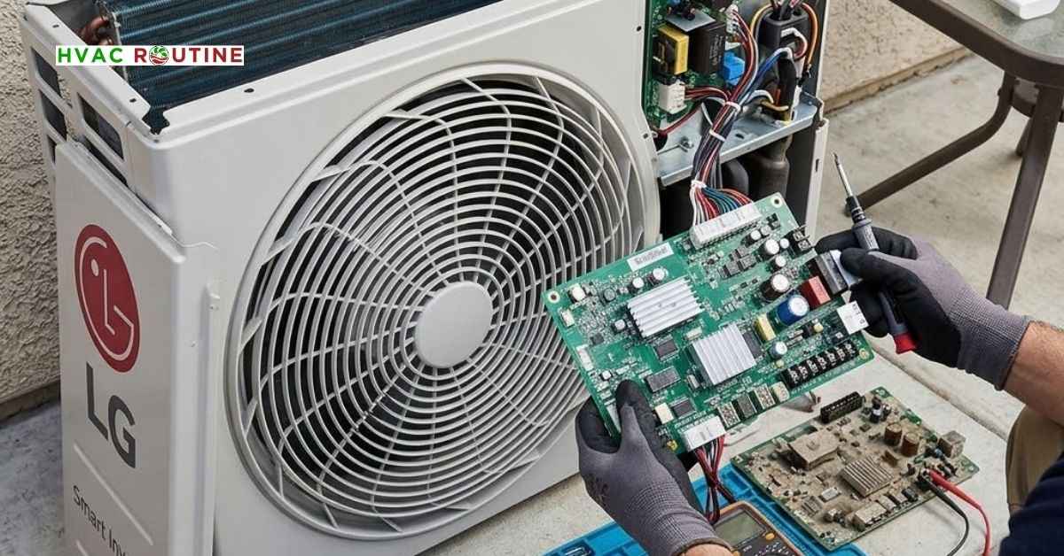
Cut power at the breaker, wait your five-minute safety window, and remove the outdoor cabinet panels to access the main inverter PCB. Locate the glass or ceramic barrel fuses mounted near the line-voltage connections. Pop each fuse gently out of its spring clip and set your multimeter to Continuity. Touch your meter probes to opposite metal ends of the fuse. A good fuse sounds a loud, continuous beep or shows near-zero resistance. A blown fuse leaves the meter completely silent with an $OL$ reading. Always replace blown fuses with the exact amperage and voltage ratings stamped on the metal end caps.
Next, shine a bright flashlight across the board’s surface. Inspect the small, 4-pin rectangular optocoupler chips positioned near the F1/F2 terminal traces for cracks, burns, or discoloration. Look for swollen electrolytic capacitors with domed tops or leaky brown crust.
- [Fuse] — Sounds Beep
- [Optocoupler] — Clean IC
- [Bulging Capacitor] — Blown Seal
- [Cracked Optocoupler] — Burn Mark
In our field calls during late spring and early summer, almost half of the dead outdoor boards we inspect don’t fail from electrical wear; they fail because of pests. Geckos, tree frogs, and carpenter ants crawl behind the warm inverter heat sinks. A single lizard bridging two high-voltage solder legs will create an arc that blows the communication rail instantly. Clean away webs, dust, or dead insects using an electronic contact cleaner spray and a soft nylon brush. Never spray WD-40 or household lubricants on your circuit boards; these products leave oily residues that attract dirt and conduct electricity, ruining the board permanently.
How to Find the Exact Samsung OEM PCB Part Number
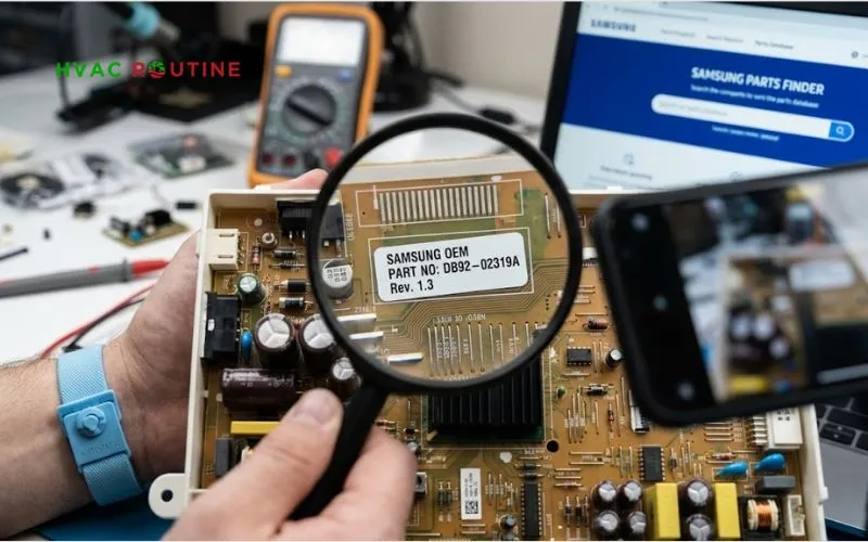
If you discover burned traces or broken optocouplers, you will need to order a replacement board. Never order a replacement PCB based solely on the general model number stamped on your air conditioner’s front plastic panel. Samsung frequently updates board revisions mid-production, and installing the wrong revision will trigger permanent, unresolvable communication errors.
Open your unit’s electrical cabinet and look directly at the green circuit board. Locate the small white barcode sticker adhered directly to the board’s surface. Search for an alphanumeric code starting with DB92- or DB93- (such as DB92-02864A or DB93-12531A). This code represents the true factory assembly part number. Order your replacement board using this exact DB92 or DB93 number through an authorized HVAC parts distributor to guarantee full firmware compatibility with your system.
Step-by-Step Fix 5: Reprogram the 24-Digit Samsung Option Code
If you recently installed a brand-new indoor replacement board, your mini-split will display an E101 error the moment you power it on. Replacement indoor boards ship from the factory with blank EEPROM chips. The unprogrammed board cannot manage the blower motor, read thermistor temperatures, or talk to the outdoor condenser until you program its identity. You can input this model-specific 24-digit hexadecimal code using your standard wireless remote control.
- Remove the batteries from your Samsung handheld remote control.
- Press and hold both the Temperature Up and Temperature Down buttons simultaneously while sliding the batteries back into the compartment.
- The remote screen will power on in Option Code Programming Mode, displaying two-digit values (
00). - Use the Mode, Fan, and Temperature buttons to select each two-character hexadecimal pair.
- Step through the screens until you enter all twenty-four characters accurately.
- Point the remote directly at the indoor evaporator unit and press the Power button.
- The indoor unit will emit a loud, musical chime to confirm that the EEPROM chip successfully saved your option code profile.
- Cycle the main breaker once to lock the configuration into memory.
How to Find Your Code If the Sticker Is Missing
If the outdoor cabinet sticker has faded in the sun or peeled away, do not guess option codes. Entering incorrect values can drive the blower motor backwards or overheat the control circuits. Locate the complete model number and serial number stamped onto the metal outdoor data plate. Contact your regional Samsung HVAC distributor or search the Samsung HVAC Partner Portal using your serial number. A technical support agent can pull the exact 24-digit factory hexadecimal string directly from the manufacturing database. You can also find this code printed inside the fold-out wiring schematic glued to the back of the outdoor electrical cover.
Step-by-Step Fix 6: Clear Multi-Zone E202 Tracking Errors
When troubleshooting an E202 error on a multi-split setup, you must manually prompt the outdoor condenser to re-inventory its connected indoor heads. The main inverter board on outdoor FJM and DVM multi-zone condensing units features miniature push buttons labeled K1, K2, and K3.
First, verify that every connected indoor head unit has active electrical power. Walk into every room to confirm that nobody turned off an isolated wall switch. Return to the outdoor condenser, press and hold the K1 button on the outdoor board for five seconds, and release it. The outdoor digital display will begin cycling characters as it runs its automated auto-addressing routine, pinging every electronic expansion valve and indoor head. Give the system five to ten minutes to complete its sweep. When finished, the outdoor display will show the total count of recognized indoor units. If you installed four indoor heads, but the display confirms only three, trace the F1/F2 lines on the missing unit.
Preventive Upgrades: Surge Protectors and Pest Guards
Once you restore your cooling, take these practical steps to protect your sensitive electronics from repeating the same failure:
- Install an HVAC Surge Protective Device (SPD): Inverter communication circuits run on sensitive direct-current millivolts and have zero tolerance for utility spikes. Mount a dedicated SPD inside or beside your outdoor disconnect box to absorb voltage spikes before they hit your board.
- Seal Cabinet Knockouts with Duct Seal: Pack ductile electrical duct seal putty around every pipe penetration, conduit entry, and knockout hole. Sealing these entry points prevents geckos, lizards, and ants from nesting on your warm inverter boards.
- Install Stainless Mesh Over Drain Holes: Fit fine stainless-steel wire mesh over the bottom cabinet drain holes to keep insects and mice out while allowing condensation to drain freely.
Estimated Repair Costs: DIY vs. Professional Service
Fixing communication errors can cost virtually nothing or require a notable investment depending on which component failed.
| Repair Scope | DIY Cost | Professional HVAC Cost |
| Power Reset / Clear Logic Glitch | $0 | $100 – $180 (Diagnostic Service Call) |
| Replace Blown Control Fuse | $5 – $15 | $120 – $220 |
| Replace 50ft Shielded Cable (16/18 AWG STP) | $35 – $70 | $180 – $350 |
| Install Dedicated HVAC Surge Protector | $60 – $110 | $220 – $380 |
| Replace Indoor Control Board (PCB) | $160 – $320 | $350 – $650 |
| Replace Outdoor Main Inverter Board | $280 – $600 | $650 – $1,200 |
Tightening a loose terminal screw, replacing a cheap barrel fuse, or running a power drain makes for an easy and satisfying weekend DIY project. On the other hand, if a major electrical storm fried your primary outdoor inverter module, paying an experienced technician to handle the high-voltage electronics is often the safest path forward.
Can low refrigerant trigger an E101 or E202 error code?
Low refrigerant charges normally trigger distinct pressure and temperature errors such as E462 (compressor current trip) or E554 (refrigerant leak detection). However, if an extreme refrigerant leak causes the compressor to overheat or trip its high-pressure cutoff within three seconds of starting, the outdoor board will shut itself down instantly. That sudden shutdown cuts off the serial data stream, creating an E101 or E202 communication fault as a secondary symptom.
Why does my mini-split wait three minutes to run after clearing the code?
Samsung systems enforce a mandatory three-minute compressor anti-short-cycle delay. This safety pause gives the high-pressure and low-pressure sides of the closed refrigerant loop time to equalize naturally before the compressor motor attempts to start against heavy backpressure.
Can I run my communication wire inside the same conduit as the line-voltage power wire?
Never run low-voltage communication wire through the same conduit pipe as high-voltage electrical lines. Alternating current running through high-voltage wires generates an electromagnetic field that induces voltage spikes on nearby wires, scrambling delicate digital data signals.
When to Call a Certified HVAC Technician
You can comfortably handle resetting circuit breakers, tightening loose terminal connections, running resistance checks on unpowered lines, and entering remote option codes. However, you should call a licensed HVAC technician if your multimeter reveals a completely dead outdoor board despite active line voltage, or if your outdoor unit trips the circuit breaker the instant power returns. Working around live 240-volt electrical connections and high-capacity direct-current storage capacitors carries serious shock hazards. Professional technicians carry specialized Samsung service software and handheld diagnostic tools that plug directly into the outdoor board to pinpoint faulty components in minutes.
Final Troubleshooting Summary
Fixing communication errors requires patience and a step-by-step diagnostic order. Always begin with a simple five-minute power reboot to clear temporary microprocessor logic freezes. Next, grab your insulated screwdriver and multimeter to verify that clean 16 or 18 AWG shielded wire connects F1 to F1 and F2 to F2 without ground loops, shorts, or loose screws. Test your live signal to confirm that your DC voltage pulses rapidly between zero and thirty volts. Finally, reprogram missing 24-digit option codes on replacement boards, or run a K1 tracking scan on multi-zone condensers. Working through these checks step by step will save you from buying expensive parts you don’t need, getting your Samsung system cooling comfortably again.

1 thought on “How to Fix the Samsung E101 Error Code (and E202) on Your Mini-Split”