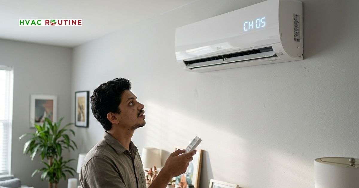
Few things test your patience like an air conditioner suddenly blowing lukewarm air and flashing an error code in the dead heat of summer. Seeing an LG CH05 error code (or “CH 05” / “C5”) on your wall thermostat or indoor display means the microprocessors stopped talking to each other.
In my years servicing ductless mini-split units, I have seen frantic homeowners ready to drop $1,500 on a brand-new compressor when the real culprit was simply a loose terminal screw or a $4 fuse. Before you assume the worst, let’s step through how to isolate the fault.
What You'll Learn ⭐⭐⭐⭐⭐
- Quick Diagnostic: What Does the CH05 Error Mean?
- How to Read the CH05 Code on Displayless LG Units
- 1. Safety Rules and Capacitor Discharge
- 2. Inspecting Terminal Block Wiring (1, 2, 3, and Ground)
- 3. How to Fix CH05 Error in LG AC with a Breaker Hard Reset
- 4. Advanced Multimeter Diagnostic Protocol
- Step A: Test Line Supply Voltage (Terminals 1 to 2)
- Step B: Test DC Communication Signal (Terminals 2 to 3)
- Step C: Ground Resistance Continuity Test (Chassis Reference)
- Step D: The Board Isolation Test (Indoor vs. Outdoor PCB)
- 5. Cable Requirements: 14/4 TC-ER and Shielding Ground Rules
- 6. Overlooked Hardware Failures: Filter Fuses and Optocouplers
- 1. Blown Fuses on the Noise Filter Board
- 2. Burned Communication Optocouplers
- 3. Pest and Moisture Damage Behind the PCB
- 7. Multi-Split Configurations: DIP Switches and Auto-Addressing
- Outdoor DIP Switch Baseline Configurations
- Executing the Auto-Addressing Procedure
- 8. Diagnostic Flowchart
- LG Mini-Split Diagnostics CH05
- 9. Symptom, Cause, and Solution Matrix
- 10. Quick Diagnostic Checklist
- 11. Repair Costs: DIY vs. Professional HVAC Contractor
- 12. When to Call a Licensed HVAC Technician
Quick Diagnostic: What Does the CH05 Error Mean?
An LG CH05 error code signals a serial communication failure between the indoor air handler and the outdoor condenser. Before buying expensive parts, switch the dual-pole circuit breaker to OFF for 5 minutes, then reapply power. If the code returns immediately, look for swapped wiring terminals, line noise on unshielded cable, a blown 3.15A filter fuse, or a damaged outdoor inverter PCB.
How to Read the CH05 Code on Displayless LG Units
If your unit is a standard LG High-Efficiency Single-Zone or an older Art Cool model without a digital temperature readout, do not worry. LG builds visual blink codes directly into the LEDs on the indoor chassis and the outdoor board.
- Indoor Operation LED (Red or Green): Stays lit or flashes once to represent the tens digit (0).
- Indoor Timer / Clean LED: Blinks 5 times consecutively, pauses for 3 seconds, and repeats the 5-blink loop. That cadence confirms Error Code 05.
- Outdoor PCB Red LED (LED01G / LD01): Pull off the top condenser panel to view the board. If the red diagnostic LED flashes 5 times in a repetitive sequence, the outdoor microprocessor is energized but receiving corrupt or missing data from indoors.
1. Safety Rules and Capacitor Discharge
Mini-split systems run on high-voltage AC mains alongside rectified DC inverter drives. Working on these requires strict safety habits.
High-Voltage DC Bus Discharge Hazard
LG inverter condensers house large electrolytic DC bus capacitors operating up to 380V DC. Even with the breaker off, these capacitors store enough energy to cause severe shock. Wait at least 10 minutes after disconnecting power for the capacitors to bleed down below 10V DC before touching internal wiring or circuit boards.
- Required PPE: Wear ANSI Z87-approved eye protection and CAT III 600V-rated electrical work gloves.
- Cut Both Power Sources: Switch off the 20A or 30A dual-pole breaker in your main electrical panel, then pull the outdoor disconnect handle at the condenser.
- Test Before Touching: Place your True-RMS digital multimeter across incoming lugs to confirm 0.0V AC before loosening any screws.
2. Inspecting Terminal Block Wiring (1, 2, 3, and Ground)
Loose or transposed wire leads cause over 50% of the CH05 service calls I run.
LG single-zone inverter systems use a 4-conductor terminal strip:

- Terminal 1 [L1]: 208V/230V AC Line 1 Power
- Terminal 2 [L2]: 208V/230V AC Line 2 Power / Neutral Reference
- Terminal 3 [Signal]: 24V–35V DC Pulsing Serial Communication
- Ground: Earth Reference Chassis Connection
- Expose Terminals and Match Points:10 minutes.
Remove the electrical covers at both units. Confirm that Terminal 1 indoors feeds Terminal 1 outdoors. Repeat this check for Terminals 2, 3, and Ground. Swapping Line 2 and Line 3 is the most frequent installation mistake—it immediately scrambles serial data.
2. Execute Mechanical Tug Tests:2 minutes.
Do not just eyeball the connection. Grab each wire and give it a firm tug. Inverter compressor vibration regularly backs terminal screws out over time.
3. Inspect Terminal Screws for Corrosion:3 minutes.
Check for rust, thermal discoloration, or moisture intrusion on the terminal block lugs. Tighten all terminals firmly using an insulated #2 screwdriver.
3. How to Fix CH05 Error in LG AC with a Breaker Hard Reset
Electrical brownouts, utility line noise, and lightning storms frequently trap microcontrollers in an unrecoverable logic loop. A hard power reset drains standby power circuits to restore baseline memory.
- Turn off the system using your LG remote control or wall thermostat.
- Switch the main HVAC double-pole circuit breaker to OFF.
- Pull out the outdoor disconnect handle at the condenser.
- Leave the power completely off for 5 to 7 minutes to allow internal standby capacitors to drop to 0V.
- Reinsert the outdoor disconnect, flip the main breaker back ON, and restart the unit via the remote.
If the indoor unit runs and blows cold air past the 3-minute mark, a transient power glitch caused the lockup. If the code flashes again immediately, move to multimeter circuit testing.
4. Advanced Multimeter Diagnostic Protocol
A True-RMS digital multimeter lets you isolate whether the problem lives in the indoor PCB, outdoor PCB, or interconnect cable.
Step A: Test Line Supply Voltage (Terminals 1 to 2)
Turn the breaker back on. Set your multimeter to AC Volts. Place test leads across Terminal 1 and Terminal 2:
- Target Reading: 208V to 240V AC.
- Troubleshooting: If voltage measures below 197V AC or fluctuates heavily, inspect your sub-panel breakers, supply lugs, and disconnect switch fuses.
Step B: Test DC Communication Signal (Terminals 2 to 3)
Switch your meter to DC Volts. Place the black probe on Terminal 2 and the red probe on Terminal 3:
- Healthy Reading: The digital display will bounce continuously between 0V DC and 65V DC (settling on an average between 24V DC and 35V DC). This pulsing voltage confirms active bidirectional data packets.
- Dead Circuit (0V DC Solid): The indoor board is not transmitting serial output, or the signal line is open.
- Stuck Circuit (Steady 65V+ DC): The communication line is floating high, indicating a failed optocoupler on the receiving PCB or a broken wire.
Step C: Ground Resistance Continuity Test (Chassis Reference)
Turn off all power at the breaker. Set your meter to Resistance ($\Omega$):
- Measure resistance between the indoor earth ground lug and the outdoor bare chassis ground screw.
- Target Reading: Less than 2.0 Ohms (ideally under 1.0 Ohm).
- If resistance exceeds 2 Ohms, ground loops or oxidation on the chassis screw are distorting the serial DC reference voltage. Clean the grounding lug down to bare metal and retighten.
Step D: The Board Isolation Test (Indoor vs. Outdoor PCB)
When the fluctuating DC signal fails, disconnect the signal wire to find the broken link:
- Turn off the breaker. Disconnect the wire landed on Terminal 3 at both the indoor and outdoor terminal blocks.
- Restore power. Place your meter leads on Terminal 2 and Terminal 3 directly on the indoor board.
- If the bare indoor board now shows the pulsing 0V to 65V DC swing, the indoor board is functional.
- Reconnect Terminal 3 indoors only. Move outside and measure between the bare end of the disconnected wire and Terminal 2. If the pulse vanishes, the cable has an internal break or short. If the pulse arrives at the outdoor end but drops to 0V the moment you screw it into outdoor Terminal 3, the outdoor main PCB communication circuit is damaged.
5. Cable Requirements: 14/4 TC-ER and Shielding Ground Rules
Standard unshielded home electrical wire (such as Romex NM-B) is unsuited for inverter mini-splits. Variable-frequency inverter compressors generate severe high-frequency electromagnetic interference (EMI). This electrical noise bleeds into unshielded signal lines, dropping communication packets.
- Required Wire Standard: Install 14 AWG, 4-Conductor Stranded Shielded Tray Cable (UL Listed Type TC-ER, CL3R, or Sun-Resistant). Never use solid-core wire; vibration causes stress fractures over time.
- Strict “No-Splice” Policy: Run a single, continuous length of cable from the indoor head to the outdoor condenser. Never join communication cables inside intermediate junction boxes or with wire nuts. A minute shift in resistance across a wire nut will corrupt digital data packets.
- Drain Wire Grounding Rule: Connect the bare metallic drain wire to the outdoor chassis ground lug only. Clip and wrap the drain wire with electrical tape at the indoor unit. Grounding the shield at both ends produces an antenna-like ground loop that amplifies noise instead of dissipating it.
6. Overlooked Hardware Failures: Filter Fuses and Optocouplers
When simple wiring checks pass, inspect these less obvious component-level issues before replacing an entire assembly.
1. Blown Fuses on the Noise Filter Board

Power feeds through a dedicated noise filter PCB before reaching the outdoor main inverter board. Utility voltage spikes regularly destroy the fast-acting ceramic fuses (rated 250V, 3.15A Time-Lag / Slow-Blow, often labeled F01G or F1) on this filter board. Pull each fuse and test continuity with your multimeter. A blown fuse cuts standby DC power to the communication transceiver.
2. Burned Communication Optocouplers
Optocouplers (commonly PC817 or similar IC chips) provide galvanic isolation between high-voltage sections and microprocessors. Power surges on the line can destroy these optocoupler transceivers while leaving the rest of the board operational. Inspect the PCB surface surrounding the Terminal 3 traces for blistered optocoupler casings, burnt surface-mount resistors, or brown heat halos.
3. Pest and Moisture Damage Behind the PCB
In outdoor condensing units, geckos, ants, and field mice frequently nest behind the main control board to seek warmth from the heatsink. If a pest bridges the high-voltage traces to the low-voltage communication circuit, it instantly destroys the serial transceiver. Check the backside of the PCB for soot marks, pest debris, or dried moisture paths.
7. Multi-Split Configurations: DIP Switches and Auto-Addressing
If your system operates multiple indoor heads on an outdoor condenser (Multi F or Multi F MAX), incorrect addressing will display CH05 or CH53 codes.
Outdoor DIP Switch Baseline Configurations
Check the 4-position or 8-position DIP switch block on the outdoor main PCB (SW01M). Ensure switches match your indoor configuration:
| Switch Position | Function | Correct Field Position |
| SW01 – Pin 1 | System Control Mode | OFF (Standard Split Mode) |
| SW01 – Pin 2 | Low Ambient Cooling Option | Set per site design (Default: OFF) |
| SW01 – Pin 3 | Compressor Frequency Restriction | OFF (Unrestricted normal operation) |
| SW01 – Pin 4 | Auto-Addressing Initialization | OFF (Flip to ON only during active address setup) |
Executing the Auto-Addressing Procedure
Run the automated address setup whenever an indoor PCB, outdoor PCB, or wiring run is modified:
- Apply continuous power to all indoor air handlers and the outdoor condenser.
- Locate the red tactile push button (SW01C / RED_SW) on the outdoor main PCB.
- Press and hold this button for 5 seconds until the outdoor 7-segment display shows “88”.
- The outdoor board will command each indoor head to run its electronic expansion valve (EEV) and register its serial address. The process finishes in 3 to 7 minutes, clearing any false CH05 or CH53 lockouts.
8. Diagnostic Flowchart
Follow this decision tree to pinpoint the failure:
LG Mini-Split Diagnostics CH05
3D Logic Flow for Inverter Serial Communication Loss
9. Symptom, Cause, and Solution Matrix
| Symptom | Probable Cause | Action |
| Code appears immediately upon restoring breaker power | Inverted wiring on Terminals 2 and 3, or severed cable | Match terminal pins 1, 2, and 3 point-to-point; replace broken wire |
| Code trips after 3–5 minutes of cooling | Electrical noise (EMI) running along unshielded cable | Run 14/4 stranded shielded cable; ground drain wire to outdoor chassis only |
| Steady 0V DC across Terminals 2 and 3 | Blown ceramic fuse or damaged indoor power supply | Test F1/F2 fuses; if fuses read open, replace fuse or indoor PCB |
| Outdoor fan and compressor fail to start | Blown noise filter fuse or fried outdoor PCB | Check 3.15A fuse on filter board; replace outdoor main board if shorted |
| Intermittent error during rain or heavy humidity | Moisture shorting corroded outdoor terminals | Dry and clean terminal lugs; replace damaged conduit seals and gaskets |
| Multi-split system shows CH05 / CH53 after board repair | Unaddressed indoor units or mismatched DIP switches | Set DIP switches to factory default and run the 5-second auto-address sequence |
10. Quick Diagnostic Checklist
Keep this checklist nearby when troubleshooting in the field:
- Dual-pole circuit breaker cycled OFF for a full 5 minutes.
- Terminals 1, 2, 3, and Ground confirmed point-to-point without wire splices.
- Terminal screws hand-checked for mechanical tightness.
- Earth ground resistance confirmed under 2.0 Ohms between units.
- Multimeter verifies fluctuating 0V to 65V DC between Terminals 2 and 3.
- Shield drain wire grounded exclusively at the outdoor condenser chassis.
- 3.15A ceramic slow-blow fuses on the noise filter PCB tested for continuity.
- Outdoor board inspected for pest intrusion, water damage, or burnt optocouplers.
11. Repair Costs: DIY vs. Professional HVAC Contractor
- DIY 250V 3.15A Ceramic Fuse Replacement: $4 to $12
- DIY 50-Foot 14/4 Shielded TC-ER Cable Run: $45 to $85
- DIY Outdoor Main Inverter PCB Assembly: $190 to $390
- Licensed Pro Diagnostic Service Fee: $125 to $225
- Licensed Pro Complete Board Replacement: $500 to $950
12. When to Call a Licensed HVAC Technician
Step back and hire a certified HVAC professional if:
- Replacement ceramic fuses blow instantly upon power-up, pointing to a dead short inside the outdoor inverter compressor windings or Intelligent Power Module (IPM).
- The main inverter PCB shows visible flame scorch marks or swollen capacitors.
- The system is covered by an active manufacturer warranty. Field-swapping circuit boards without factory authorization can void your remaining parts protection.